Your partner for all differential pressure measurement products
and accessories within the energy value chain
Flow Nozzles™ ASME PTC6
1 Primary Flow Measurement1.1
The accurate determination of primary flow to the
turbine is necessary to compute turbine heat rate or
steam rate if the results are to be considered as a basis
for turbine acceptance. Recognizing the limitations presented
herein, this Code recommends measurement of
water flow in the feedwater cycle. Extreme care must be
taken to obtain the high order of accuracy necessary in
primary water-flow measurement. Any deviation from
the requirements set forth in the following paragraphs
may result in an increase in uncertainty. All known errors
must be reduced so that their individual effect is
less than 0.05% of the primary flow to be measured.
1.2 Measurement of Water Flow
While weighing of water can be the most accurate
method of measuring flow, it is seldom practical or economical
to employ weigh tanks or volumetric tanks for
testing of the large units installed in modern power
plants. The usual method of determining flow is with a
differential pressure producing device. Two sets of pressure
taps and a differential pressure instrument for each
set of taps will be used.
1.3 Recommended Method
Excellent results have been obtained using low-beta-ratio
throat-tap nozzles, and, for this reason, this Code recommends
that they be used. The stringent requirements
for the recommended primary flow device contained in
this Code are based on experience with the low-beta-ratio
throat-tap nozzles installed in 4 in. to 28 in. flow sections.
Larger flow sections may be used provided they can
be calibrated in accordance with paras. 1.13 and 1.14.
1.4 Flow Section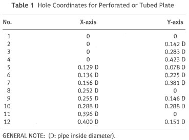 Throat-tap nozzles are recommended for measurement
of primary flow provided they comply with the
following requirements:
Throat-tap nozzles are recommended for measurement
of primary flow provided they comply with the
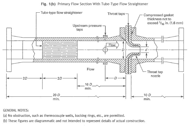
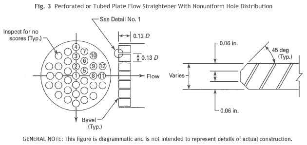
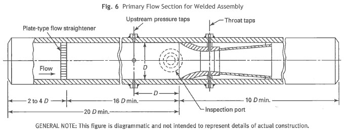
following requirements:(a) The beta-ratio (d/D) is limited to the range of 0.25 to 0.50. (b) The test flow section shall be calibrated (see paras. 1.13,1.14 and 1.15). The flow section is comprised of the primary element, including the diffusing section, if used, and the upstream and downstream pipe sections. The upstream pipe section shall be a minimum of 20 diameters of straight pipe and include a flow straightener installed at least 16 pipe diameters upstream of the primary element. The preferred flow straightener utilizes a low-pressure drop perforated or tubed plate with a nonuniform hole distribution. The geometry of the design is shown in Fig. 3, and hole coordinates are specified in Table 1. The design and hole coordinates are identical for both the perforated and tubed plate straightener. The upstream side of the holes must be beveled in all cases. The straightener is located between 2 and 4 diameters downstream of the test flow section inlet, as shown in Fig. 1(a). An alternative is a perforated-plate flow straightener, as shown in PTC 19.5, Flow Measurement. However, because it is likely to have a higher pressure drop, there is an increased chance of cavitation in the nozzle during calibration, which may limit the maximum Reynolds Number achieved. Another acceptable design, utilizing a bundle of at least 50 tubes 20 long (see Fig. 1(b)), has been used extensively. Other types of flow straighteners may be used if their ability to remove swirl and distortion from the upstream flow has been demonstrated. (c) The primary flow element and its flow section shall be known to be clean (see para. 1.18) and undamaged throughout the test period. This shall be determined by inspection as soon as possible before and after the test. The location of the primary flow section in the cycle, its physical configuration, and the technique that is employed to obtain the flow measurements are critical and discussed in subsequent paragraphs. 
1.5
PTC 19.5 contains a description of the low-beta-ratio
throat-tap nozzle; however, additional information is included
in the following paragraphs that applies specifically
to throat-tap nozzles used for steam turbine testing.
PTC 19.5 also contains procedures for ca1culating
the flow of water through a throat-tap nozzle using
measured values of pressure differential between an inline
set of upstream and throat taps.
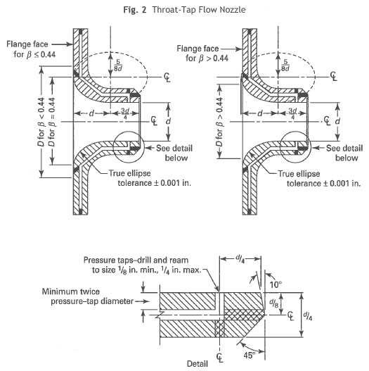
1.6 Design and Manufacture
Because of the high degree of accuracy necessary, the
following requirements are given in regard to the design
and manufacture of throat-tap nozzles for primary
flow measurement. Fig. 2 of this Code and PTC 19.5
show examples of long-radius, low-beta-ratio nozzle
shapes with throat taps that satisfy these requirements.
It is recommended that this nozzle be manufactured
with four throat taps, located 90 deg apart.
Great care must be taken in the manufacture and inspection of throat-tap nozzles, particularly in regard to the geometry of the nozzle and downstream pressure taps; otherwise, difficulties meeting the calibration criteria may occur. This is particularly true when the flow section is welded together, since problems with calibration will not be evident until after the nozzle has been welded into the upstream and downstream pipe sections. Any required rework of the nozzle would obviously be much more difficult than with a flanged construction. 1.7
The entrance provided by the low-beta-ratio profile
gives a favorable pressure gradient so that the boundary
layer will be very thin in the throat section and there
will be no flow separations. The area in the plane of the
throat taps shall be used in the coefficient ca1culation.
The nozzle shall be made from a corrosion-resistant material
with known thermal expansion coefficient, and its
surface shall be free of all burrs, scratches, imperfections,
or ripples. The surface should be either "hydraulically
smooth" or 16 μ in., whichever is smoother.
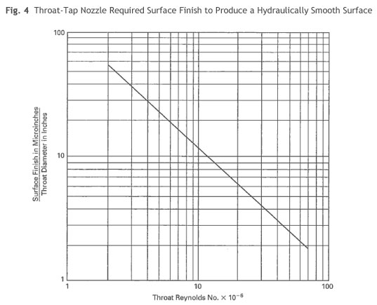
For turbulent boundary layers, the surface is "hydraulically
smooth" when protuberances are contained
within the laminar sublayer. Figure 4 presents the surface
finish necessary to be hydraulically smooth as a
function of throat diameter and the maximum throat
Reynolds number achieved during either test or calibration.
1.8
To minimize instrument systematic error, the nozzle
throat diameter should be selected to give the maximum
deflection possible, considering both the available
pumping head and instrument range. The transducer or
manometer range should be selected to allow for fluctuations
and maximum flow which may be encountered.
The nozzle shall not be used to measure flow
when the differential pressure is fewer than 1000 times
the reading error, or 2.5 psi (17.2 kPa), whichever is
larger. When it is necessary to measure flow over a
larger range than can be obtained by complying with
this requirement, it is permissible to use additional nozzles
with different throat diameters. These nozzles
should be sized so that one of the test points can be run
with each nozzle.
When measuring large flows, the nozzle is sometimes sized to give large pressure differentials with correspondingly large unrecoverable losses. A large pressure drop may prevent normal operation of the plant and will represent a penalty in cyc1e efficiency, which may be unacceptable if the nozzle is to be installed for a significant period of time. This loss can be reduced by about 70% by installing a diffuser downstream of the nozzle as shown in Fig. 5(a). This figure is for a typical diffusing cone installation showing flow-path requirements and not intended to show details of mechanical design. A cylindrical section of length d/2 preceding the diffuser is necessary in order not to change the flow coefficient. Care should be taken to see that the cylindrical section of the diffusing element does not protrude into the flow from the throat of the nozzle and that the gap between nozzle and cylindrical section is fewer than 0.050 in. The calibration must be made with the diffusing section in place. It is recommended that the diffuser material have the same expansion characteristics as the nozzle. A secondary benefit of a diffusing cone may occur during calibration. With a reduced unrecoverable pressure loss, the calibration facility may be able to achieve a higher Reynolds number. 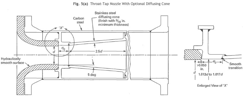
1.9 Pressure Taps
The pressure taps shall be between 1/8 in. (3 mm) and
1/4 in. (6 mm) in diameter and at least two pressure-tap
diameters deep. They shall be machined perpendicular
to the surface, have sharp corners, and be free from
burrs and scratches. The downstream pressure taps shall
be machined in the throat of the nozzle in order to decrease
the effect of downstream disturbances on this
pressure measurement. They shall be drilled and
reamed previous to the final boring and polishing of the
throat. A plug with a press fit is then inserted in the
hole. The final boring and polishing operation should
be done after the insertion of the plug. The plug should
be made with provisions for pulling it out of the hole
after the polishing and machining is completed. After
removal of this plug, any slight burr that might be left
on the edge of the hole may be removed by using a tapered
piece of hardwood, such as maple, to roll around
the tap edges. The upstream taps shall be carefully made
and located one inside-pipe diameter upstream from the
nozzle entrance.
1.10 Pipe Section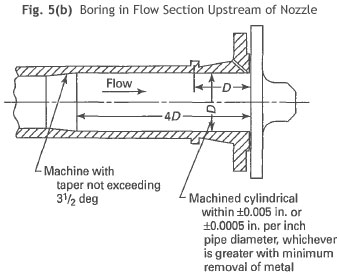 The pipe on either side of the flow nozzle shall be
smooth, and free from rust, scale, and blisters. For the
upstream pipe section, the inside diameter measured at
four points at any cross-section shall not differ by more
than 0.2%. The average inside diameter at different
cross-sections shall not differ by more than 1%. The allowable
variations in inside diameter for the downstream
pipe shall be twice those for the upstream pipe
section (see Fig. 5(b)).
The pipe on either side of the flow nozzle shall be
smooth, and free from rust, scale, and blisters. For the
upstream pipe section, the inside diameter measured at
four points at any cross-section shall not differ by more
than 0.2%. The average inside diameter at different
cross-sections shall not differ by more than 1%. The allowable
variations in inside diameter for the downstream
pipe shall be twice those for the upstream pipe
section (see Fig. 5(b)).The upstream pipe must be machined cylindrical within ±0.005 in. or ±0.0005 in. per inch of pipe diameter, whichever is greater, with minimum removal of metal for a length of at least four pipe diameters, and then tapered at 3.5 deg to the remaining pipe inside diameter. 1.11 Flanged AssembliesFlanged assemblies are normally used with relatively low pressures, such as when the flow element is in the condensate line upstream of the main feed pump. This arrangement is associated with the recommended procedure for the full-scale test. The flow nozzle shall be centered in the pipe within 1/32 in. (0.8 mm) of the pipe axis.If the flow section is downstream of the main feed pumps where it is subject to high-pressure levels, flanges should conform with the pressure-temperature rating in ANSI B16.5, Pipe Flanges and Flanged Fittings: NPS through NPS 24. Considerations, such as the cost of the flange s, the cost of moving them into place, and the added cost of pipe hangers, may make it desirable to use a welded assembly (see para. 1.12). When the flow section is assembled with flanged connections, the pipe joints at the flow nozzle shall have the inner bores square with the faces of the flanges. The gap between the nozzle and pipe flanges shall not exceed 1/16 in. (1.6 mm). The gaskets shall not extend within the pipe. Flanges adjacent to the nozzle should be provided with dowels or other means to ensure that all components of the complete flow section are always assembled in exactly the same relative locations as when it was calibrated. Some methods of manufacture may subject the nozzle throat to distortion due to thermally induced stress. This could be caused by the difference in linear expansion coefficients for the different materials of the components. To reduce the possibility of thermal distortion of the nozzle, it is desirable that the pipe and flanges of the flow section adjacent to the nozzle be made of a material having the same coefficient of expansion as the nozzle. To avoid damage to the nozzle during flushing that normally precedes the initial startup of the plant, it is recommended that the flow section be installed after flushing. 1.12 Welded Assembly
If the flow section is downstream of the main feed
pumps where it is subject to high-pressure levels, it may
be welded together and then be welded in the station
piping after the piping has been flushed. A typical of
such flow section is shown in Fig. 6. To meet the requirement
of inspecting the nozzle both before and after
a test, a welded flow section shall include a plugged
inspection port immediately upstream of the nozzle. The
orientation of the inspection port will be determined by
the ease of inspection, ease of cleaning, and other design
considerations. An example of such an inspection
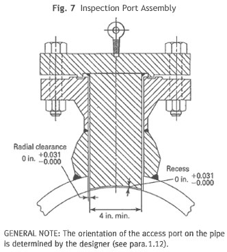
port is shown in Fig. 7. The inside diameter of the inspection
port should be at least 4 in. (100 mm) to allow
easy access and nozzle cleaning if required.
 The inspection device (typically a fiber optic device)
shall not damage the sharp edges of the inspection hole
or the surface of the nozzle, particularly around the taps.
The plug must be undamaged, and the contour of the
plug must be properly aligned to preserve the flow profile
of the water. A plug radial clearance of up to 1/32 in.
(0.8 mm) will be acceptable. A recess (i.e., distance from
the end of the plug to the inside diameter of the pipe)
of up to 1/32 in. (0.8 mm) is acceptable. The plug must
not protrude into the pipe.
The inspection device (typically a fiber optic device)
shall not damage the sharp edges of the inspection hole
or the surface of the nozzle, particularly around the taps.
The plug must be undamaged, and the contour of the
plug must be properly aligned to preserve the flow profile
of the water. A plug radial clearance of up to 1/32 in.
(0.8 mm) will be acceptable. A recess (i.e., distance from
the end of the plug to the inside diameter of the pipe)
of up to 1/32 in. (0.8 mm) is acceptable. The plug must
not protrude into the pipe.For flow sections welded into the feedwater pipe, the flow nozzle must be constructed of a corrosion resistant material if the pipe is subject to chemical cleaning. The cleaning of the flow test section can be accomplished by the use of very high-pressure water jet devices. In the design of the plant, the design of available cleaning devices should be reviewed, and the practicality of performing the cleaning through the inspection port should be evaluated. It may be advisable to install a special port downstream of the downstream pipe section specifically for the introduction of a high-pressure water leaning device. If, after installation, inspection reveals damage to the flow nozzle or its throat taps, such damage may be remedied through the access provided by the inspection opening. This would depend on the type and extent of the damage and call for consultation and agreement between the parties to the test. Precaution should be taken to avoid nozzle throat distortion in service due to use of materials with dissimilar thermal expansion characteristics. 1.13 Calibration
Experience shows that the coefficient of discharge for
a particular flow section cannot be satisfactorily predicted
to meet Code uncertainty objectives, and, therefore, it is
necessary to calibrate each flow section. This calibration
should be undertaken only at recognized facilities under
conditions similar to those in the actual installation. Care
must be exercised in the selection of the calibration facility
and analysis of the calibration data to ensure that the
single-point accuracy necessary to establish the slope of
the calibration curve is attained. The physical construction
of the piping in the calibrating setup should be similar
to that in the test setup from the standpoint of pipe
configuration, immediately upstream and downstream of
the flow-measuring section. Also, the Reynolds number,
water temperature, and other flow conditions should be
as dose to test conditions as possible. The calibration
should preferably consist of at least 20 acceptable points
over a wide range of Reynolds numbers. If repeat calibration
points at the same Reynolds number differ by
more than 0.1%, an additional calibration point at the
same Reynolds number is recommended. When it is not
possible to calibrate at test Reynolds number, it is permissible
to extrapolate the calibration curve as described
in para. 1.16. Since the effect of the transition region becomes
increasingly smaller as Reynolds number rises,
this Code recommends that the value of the coefficient
be established at highest Reynolds number possible so
that this effect is minimal. AH four tap sets should be calibrated.
For the test, select the two tap sets that most
closely comply with first, the calibration criteria (see
paras. 1.13, 1.14, and 1.15) and second, the guidelines
in Fig. 11. Each selected tap set shall be instrumented
individually. If the calibration of the flow section
does not comply with para. 1.14, the nozzle should be
carefully inspected as described in para. 1.7, and corrected,
il necessary, and the flow section recalibrated. If
the recalibration still does not comply with para. 1.14,
the flow section should again be recalibrated using different
facilities. In the event different facilities are not
available, the parties to the test must agree on the course
of action before the test is started.
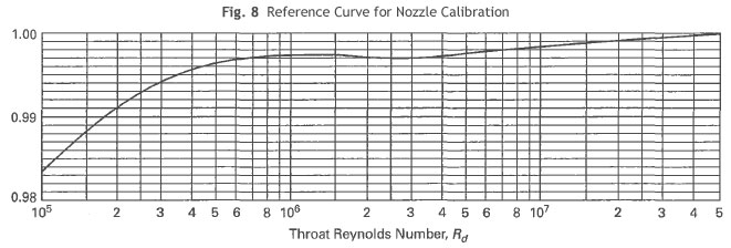
1.14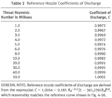 Compliance with the requirements of paras. 1.4
through 1.12 is determined by the shape of the coefficient
of discharge,
Compliance with the requirements of paras. 1.4
through 1.12 is determined by the shape of the coefficient
of discharge,  , versus Reynolds number curve established
by calibration. For each set of selected taps,
the calibration curve (not necessarily each individual
point) shall be within 0.25% of the reference curve (see
reference curve Fig. 8 and Table 2) and meet the
criteria of para. 1.15. The reference curve shown in Fig.
8 was derived from a detailed boundary layer analysis
and corroborated later by a study yielding the expression
given in Table 2. The equation, discussed in
para. 1.15, is a description of the coefficient of discharge,
, of a throat-tap device throughout the entire
range of Reynolds numbers of interest. , versus Reynolds number curve established
by calibration. For each set of selected taps,
the calibration curve (not necessarily each individual
point) shall be within 0.25% of the reference curve (see
reference curve Fig. 8 and Table 2) and meet the
criteria of para. 1.15. The reference curve shown in Fig.
8 was derived from a detailed boundary layer analysis
and corroborated later by a study yielding the expression
given in Table 2. The equation, discussed in
para. 1.15, is a description of the coefficient of discharge,
, of a throat-tap device throughout the entire
range of Reynolds numbers of interest.
1.15 Evaluation of Laboratory Calibration DataThe recommended method for determining if the calibration data of a throat-tap nozzle is satisfactory, i.e., can be extrapolated parallel to the reference curve as required in para. 1.14, is as follows:Make multiple solutions of an equation of the form  and evaluating for and evaluating for
 . Three criteria
must be satisfied for the nozzle calibration to be accepted
as satisfactory. . Three criteria
must be satisfied for the nozzle calibration to be accepted
as satisfactory.
1.15.1 Average Value. The average value of
must equal 1.0054 ± 0.0025 (therefore, 1.0079 >= >= 1.0029).
1.15.2 Reynolds Number Independence. The values of
must show no dependence on  .
This is determined by an unconstrained linear regression of
(least squares fit) represented by the equation .
This is determined by an unconstrained linear regression of
(least squares fit) represented by the equation  .
If the slope of the unconstrained fit, .
If the slope of the unconstrained fit,  , is within ±2.7E-10, the values of ex may be considered
independent (or have an acceptable
degree of dependence). , is within ±2.7E-10, the values of ex may be considered
independent (or have an acceptable
degree of dependence).
If the flow section is to be used within its calibration range, the curve obtained from the calibration data can be used even if its slope does not meet this Reynolds number independence criterion. Guidance on performing regression analysis may be found in PTC 19.1, texts on statistical analysis, and ISO 7066-1 1989, "Assessment of Uncertainty in the Calibration and Use of Flow Measurement Devices-Part 1. Linear Calibration Relationships."
1.15.3 Scatter of Calibration Data. The confidence
interval of the
data for 95% confidence level
should not exceed 0.0006 (±0.0003 from the regression
line of ). If this is not achieved with the recommended
20 calibration points, it will be necessary to collect additional
calibration points.
If there is excessive scatter in the calibration data, the
nozzle should be inspected, reworked, and recalibrated.
If scatter is still present, another nozzle shall be used for
the test.
1.16 Extrapolation
When an extrapolation of calibrated data to higher
Reynolds numbers is required, as permitted by para.
1.13, that extrapolation shall be made by solving for
at test Reynolds number in the equation in para.
1.15 with equal to the average value determined
for the set of calibration data being used. This method
provides a precise and repeatable means for determining
a coefficient of discharge beyond the upper limit of
the calibration range.
1.17 Transition Region
At low-throat Reynolds numbers, the nozzle boundary
layer is laminar; at high-throat Reynolds numbers,
it is turbulent. In between these two regions is a zone
called the transition region. Figs. 8 and Table 2 indicate
that for Reynolds numbers between 1 and 4 million,
nozzle coefficients described in this Code are noticeably
affected by the transition of the boundary layer.
However, experience has shown that for any given nozzle,
coefficients in this region are repeatable within laboratory
random. Therefore, the coefficient of discharge
in this region is stable and usable for any calibrated nozzle
that meets the evaluation criteria in para. 1.15. It
is recommended that nozzles be sized to produce throat
Reynolds numbers beyond this range if possible and extrapolation
be performed as described in para. 1.16.
1.18 Deposits
A slight iron-oxide film on the nozzle surface will
usually collect during the test. If film thickness is fewer
than 0.0002d, and uniforrnly deposited, its effect on the
uncertainty of the flow measurement will be negligible.
If the thickness of the deposit exceeds this value, or if the nature of the deposit is nonuniform and the surface appears rough, either of two procedures may be followed: (a) the nozzle may be cleaned using commercial cleaning agents or fine rubbing compounds not harmful to the nozzle and the test repeated; or (b) the flow measuring section may be recalibrated, and if the calibration change is judged to be insignificant by the parties to the test, they should agree on the action to be taken. Care must be taken not to disturb the deposit before recalibration. If the calibration is significantly different from the calibration prior to the test, it is necessary that another set of runs be made under deposit-free conditions. The test results cannot be adjusted, since it is usually impossible to determine when the deposit formed on the nozzle. Removable flow sections should be installed, at a practicable time, to minimize the interval between installation and test dates. 2 Installation of Flow Section2.1 Recommended Cycle Locations
This Code provides
a choice for the location of the primary flow measurement.
Variations in flow measurement locations may be
used by agreement between the parties to the test provided
precautions are taken to eliminate heater leakage
and recirculation flows and appropriate instrumentation
is installed.
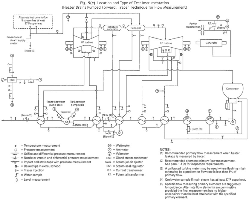
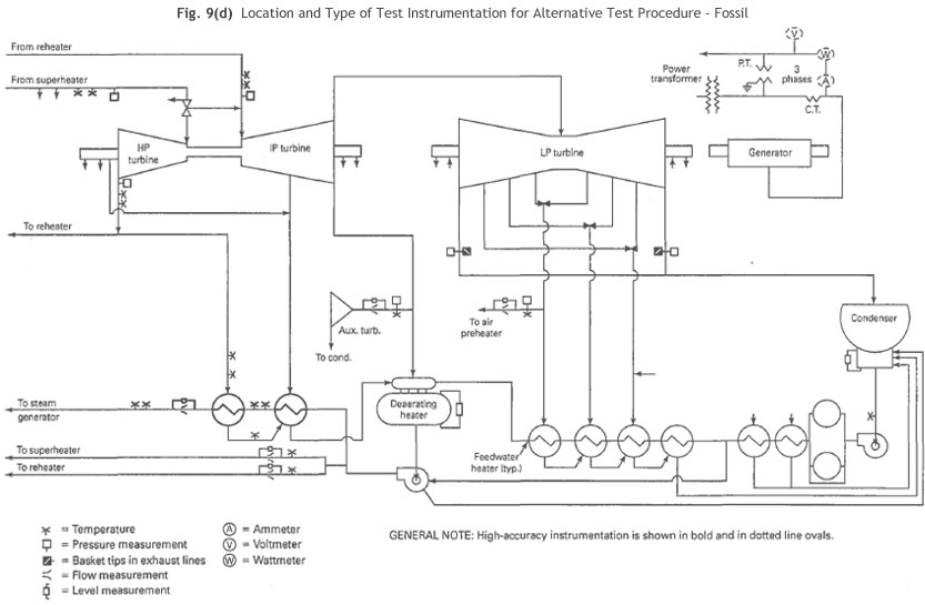
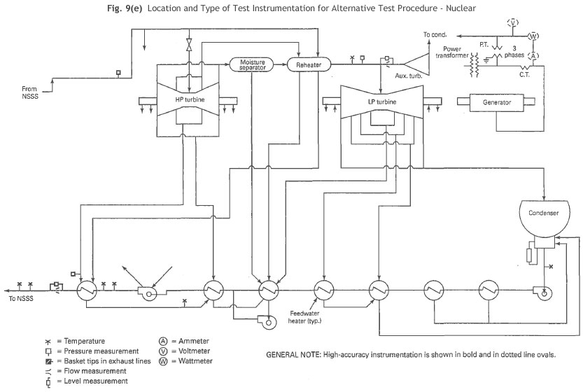
Figures 9(a) through 9(e) show the location of flow instrumentation in typical cycles. While these diagrams show only single strings of heaters, two or three strings are commonly used with the larger sized turbine- generator units. For cycles of large units and particularly those with nuclear steam supply systems, two or more flow measuring devices may be used in parallel at each primary flow location. 2.2 Condensate Flow Section
(a) For units with high-pressure feedwater heaters
supplied with superheated extraction steam, see Fig.
9(a). If the feedwater cycle has a deaerator, it is recommended
that condensate flow entering it be measured
as primary flow. This eliminates the possibility of
any heater tube leakage recirculating through the flow
measuring device.
If the feedwater cycle has no deaerator but does have a heater with pumped-ahead drains immediately upstream of the feedwater pump, it is recommended that the condensate flow entering this heater be measured. Again, there is no possibility of heater tube leakage recirculating through the flow measuring device. If the feedwater cycle has no deaerator nor pumped-ahead heater drains immediately upstream of the feedwater pump, it is recommended that condensate flow be measured downstream of the low-pressure heaters and upstream of the feedwater pump. If the absence of high-pressure heater leakage is not verified by use of a suitable tracer or other technique, it will be necessary to measure the total drain flow from the high-pressure heaters for comparison with the sum of the extraction flows from these heaters as calculated by heat balance. The difference between these values is the amount of suspected high-pressure heater leakage. The preceding primary flow locations were selected to improve the accuracy of the measurement by (1) avoiding difficulties associated with use of flanged joints in high-pressure piping, (2) taking advantage of lower water temperatures that minimize the extrapolation of the coefficient-of-discharge curve, and (3) avoiding complications created by possible recirculating flows through the primary flow section. (b) For units with high-pressure feedwater heaters supplied with wet extraction steam, see Fig. 9(b) and (c). If the feedwater cycle has a heater with pumped-ahead drains upstream of the feedwater pump (Fig. 9(b)), it is recommended that the condensate and heater drain flows both be measured immediately upstream of the point where they mix and the sum of the two flows be used as primary flow, provided that the absence of heater leakage is verified by use of a suitable tracer technique. Otherwise, the feedwater flow from the highest pressure heater also must be measured for comparison with the primary flow with adjustrnent for feedwater pump injection and leak-off flows. The difference between these values is the amount of suspected high-pressure heater leakage. If the feedwater cycle has only heaters with drains cascading to the condenser (Fig. 9(c) - Note (I)), it is recommended that feedwater pump suction flow be measured, provided that the absence of heater leakage is verified by use of a suitable tracer technique. Otherwise, feedwater flow from the highest pressure heater must be measured for determination of suspected water leakage, as in the case of the intermediate pumped-ahead-heater cycle. When measuring feedwater pump suction flow, use of a metering pressure drop that infringes on the pump required minimum NPSH should be avoided. (c) Before aborting or discarding a test because of suspected high heater leakage , the isolation of the cycle should be rechecked, calibration curves of the flow measuring devices investigated, and possibility of error in the final feedwater or heater drain flow measurements considered. 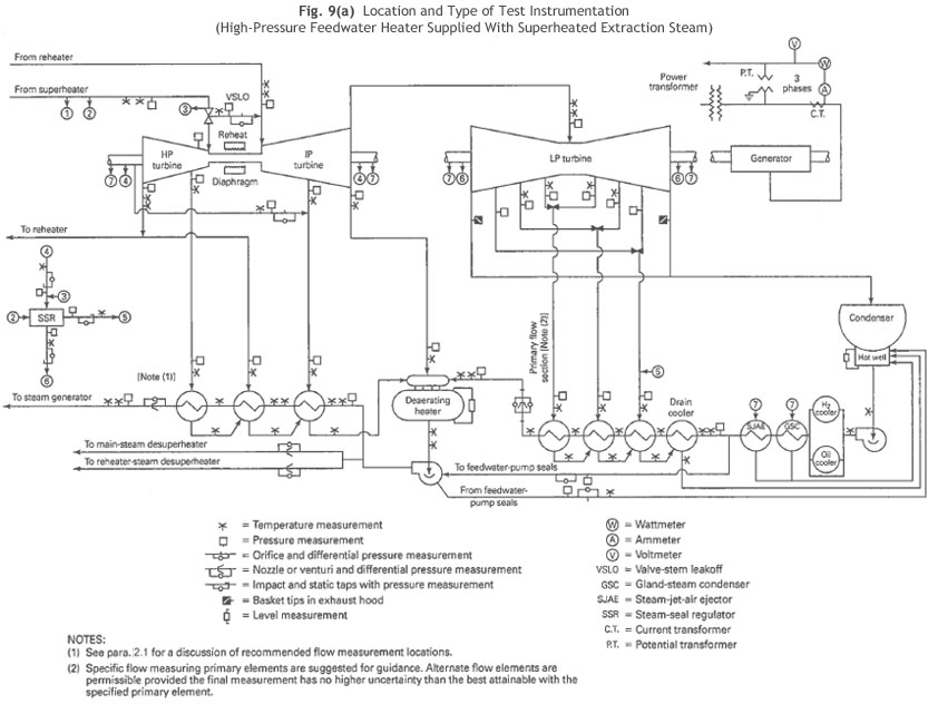

2.3 Feedwater Flow Section
The primary flow measuring device is installed, perhaps
welded, in the feedwater line, downstream of the
highest pressure heater, so that it directly measures
feedwater flow to the steam generator.
2.4
To minimize the difficulty of obtaining steady flow,
the flow measuring device should not be located at a
pump discharge. Advantage should be taken of the
damping effect of any existing heat exchangers and long
lengths of pipe in the cycle in locating the flow measuring
device. The flow measuring device should also
be located to eliminate the effects of recirculating and
bypassing flows. If this is not possible, extraneous flows
shall be measured with sufficient accuracy so that the
effect on primary flow uncertainty is fewer than ±0.05%.
2.5
The installation of the flow measuring section in a horizontal
run is recommended. To minimize the effects of
distortion due to thermal expansion and nozzle-coefficient
extrapolation due to higher Reynolds numbers,
flow nozzle locations having water temperatures below
300°F (422K) are preferred. However, flow nozzles located
downstream of the highest pressure heater are acceptable
if they are designed in accordance with this
Code (see paras. 1.6 through 1.18).
2.6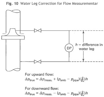 When the flow measuring device is installed such that
the upstream and downstream tap locations are at different
elevations, it is necessary to correct for water leg
differences between the tap elevations caused by the difference
in density of the water in the flow section and
pressure-sensing lines (see Fig. 10).
When the flow measuring device is installed such that
the upstream and downstream tap locations are at different
elevations, it is necessary to correct for water leg
differences between the tap elevations caused by the difference
in density of the water in the flow section and
pressure-sensing lines (see Fig. 10).
2.7If the only two acceptable sets of taps are 90 deg apart instead of the recommended 180 deg apart in a horizontal pipe, one set should be located at the horizontal axis of the pipe (see Fig. 11). If the other set of taps has the upstream and down-stream taps connected to the pipe at different elevations, special attention to insulation must be given to minimize any specific weight differences between the water flowing through the pipe and in the pressure tap lines (see para. 2.6 and Fig. 10). If the flow section is located in a vertical pipe, any tap configuration is acceptable. See para. 2.6 for further discussion of necessary water leg correction for taps at different elevations.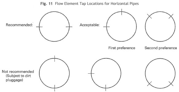
3 Flow Characteristics3.1
Flow measurements shall not be undertaken unless the
flow is steady or fluctuates only slightly with time. The permissible magnitude of mass flow
fluctuation requires that the magnitude of the differential
pressure fluctuation, (max - min)/2, not exceed 1%
of the average for fluctuation frequencies greater than or
equal to twice the sampling rate. For fluctuation frequencies
less than twice the sampling rate, the permissible
limit of the fluctuation in differential pressure is 4%.
Fluctuations in the flow shall be suppressed before the
beginning of a test by very careful adjustment of flow and
level controls or introducing a combination of conductance,
such as pump recirculation, and resistance, such as
throttling the pump discharge, in the line between the
pulsation sources and flow measuring device. Damping
devices on instruments do not eliminate errors due to pulsations
and, therefore, shall not be used. If the pulsations
exceed the above values after every effort has been made
to suppress them, mutual agreement is required before
the test can proceed.
3.2
In passing through the flow measuring device, the
water shall not flash into steam. The minimum throat
static pressure shall be higher than the saturation pressure
corresponding to the temperature of the flowing
water by at least 20% of the throat velocity head, as required
per para. 9.2, to avoid cavitation.
4 Other Flow-Measuring Devices
Information relative to the construction, calibration,
and installation of other flow-measuring devices is described
in PTC 19.5. Although these devices are not recommended
for the measurement of primary flow, they
may be used provided they conform to the general requirements
of paras. 1.4 and 1.14 with the following
exceptions:
(a) For the requirement stated in para. 1.4(a), the beta-ratio shall be limited to the range 0.25 to 0.50 for wall-tap nozzles and venturis and 0.30 to 0.60 for orifices. (b) For the requirement stated in para. 1.14, the appropriate reference coefficient for the actual device given in PTC 19.5 shall be used. The parties to a test should become familiar with the contents of PTC 19.5 regarding these devices. 5 Measurement of Steam Flow5.1
This Code requires that the primary flow be measured
in the feedwater cycle (para. 2) whenever possible.
When the cycle configuration requires primary
steam flow measurement, the requirements for accurate
steam flow measurements are the same as for water flow
measurements with the exceptions and additions of
paras. 5.2 through 5.5. The installation and calibration
of flow measuring devices used to measure primary
steam flow to high-pressure, high-temperature
turbines, however, is inherently difficult.
5.2 Installation
The installation shall be in accordance with PTC 19.5.
Valve stems should be in the horizontal position to prevent
trapping of water.
5.3
The flow section shall have the same thermal insulation
as the rest of the steam pipe.
5.4 Flow Characteristics
In passing through the flow measuring device, the
steam shall remain superheated. Measurement shall not
be attempted if the amount of superheat is less than 27°F
(15K) in the throat.
5.5 Secondary Measurements
The calculation of steam flow through a nozzle, an
orifice, or a venturi should be based on upstream conditions
of pressure, temperature, and viscosity. In order
to avoid the disturbing influence of a thermowell located
upstream of a primary element, downstream
measurements of pressure and temperature are used to
determine the enthalpy of the steam, which is assumed
to be constant throughout a well-insulated flow measurement
section. Based on this enthalpy and the upstream
pressure, the desired upstream properties can be
computed from steam tables.
6 Measurement of Water Flow Using Tanks6.1
Actual weighing of water is the most accurate method
of measuring flow if the tanks, timing devices, and
scales are sized and calibrated to eliminate total measurement
uncertainty of 1% or greater. It is sometimes
necessary to load and unload large scales many times before
an accurate scale calibration can be obtained.
6.2
Volume tanks also give accurate results provided that
they are properly maintained and calibrated. Temperature
corrections should be applied to account for changes
in tank size.
6.3
The following precautions shall be observed in the use
of weigh or volume tanks:
(a) There shall be no spilling or loss of water at admission whenever two tanks are used. Whatever means are employed for diverting water from one tank to another shall be quick, positive, and symmetrical. (b) Should the method of measurement require level indicating means, the arrangement of the tank or tanks shall be such that the level may be observed with an accuracy that will limit the total measurement uncertainty to less than 20.1 of the contents of the tank, including errors of observation incidental to turbulences caused by the maximum rate of incoming water flow. (c) It shall be ascertained that inlet and outlet valves or gates do not leak when closed. (d) It shall be ascertained that the weighing tank system is free from any external force and that nothing can affect the weight reading except the deadweight, or tare, of the tank and the water to be weighed. The deadweight, or tare, shall be taken before each filling. (e) Volume tanks must cease dripping before the outlet valves are closed. (f) In order that any inconsistency in the quantity measurements may be immediately discovered, equal time periods or equal weight increments should preferably be alloted for charging weigh tanks. (g) For weigh tanks, the weight of air displaced by water shall be taken into account. (h) The method of accounting for losses in the form of flash vapor shall be agreed upon. (i) The density of water in the volume tanks should be determined from a temperature measurement accurate to within ±1°F (0.5 K). 7 Differential-Pressure Measurements7.1
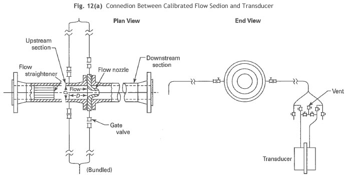
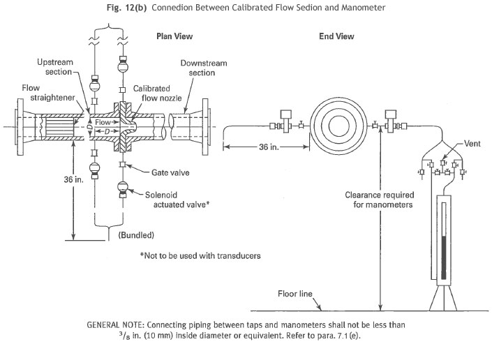
The measurement of the differential pressure necessitates
particular care. Some precautions are listed below
and illustrated in Fig. 12(a) and (b).
(a) Calibrated differential pressure transducers are
recommended. A transducer for each set of taps is required.
For primary flow measurements, differential
pressure transducers of the 0.05% (or better) accuracy
class (kO.l % maximum uncertainty) shall be used. The
length of piping between the flow measuring device and
manometers shall not exceed 25 ft (7.5 m) and shall be
uninsulated. Piping to transducers may be longer than
25 ft (7.5 m) and shall be uninsulated.
(b) For primary flow measurements, differential pressure transducers should not introduce an uncertainty exceeding ±O.1 % of the minimum flow to be measured. They must be calibrated before and after each test, and each calibration must be accomplished for both increasing and decreasing pressure in order to establish hysteresis. If one-half the hysteresis error is small enough to allow use of the transducer, the mean curve between the two calibration curves shall be used for correcting the observed pressure. The aging of the transducer must be carefully recorded. The before and after calibration curves shall not differ by more than 0.05% of mass flow. Except by agreement of the parties to a test, the test must be repeated if this difference is exceeded. It is advisable to use transducers which have stable characteristics over the span of the test period. (c) In order to achieve and maintain the desired accuracy, transducers may require shock mounting and a temperature-controlled environment during the test. All transducers shall be bench calibrated at line pressure using a calibration reference that is traceable to a recognized national standards laboratory, such as the National Institute of Standards and Technology. After installation for the test, a zero reading shall be obtained at line pressure. (d) In nuclear applications, transducers may be mounted in areas of high radioactivity. Pressure lines run from the transducers to an area of low radioactivity allow the transducers to be calibrated in place. Appropriate remotely controlled valves with the same flow resistance in each direction must be used (see Fig. 13). 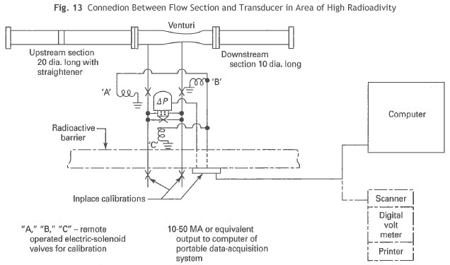
(e) For manometers, connecting piping used between
the pressure taps and the instruments shall not be less
than 3/8 in. (10 mm) inside diameter tubing or equivalent
to avoid resistance damping inside the piping. This
tubing shall run horizontally for 3 ft (1 m) from the flow
measuring device and then slope down continuously
without loops to the instrument in order to eliminate air
from the lines.
(f) Precaution must be taken when running the instrument piping to ensure that the temperature difference of the fluid in the two lines connecting the primary element and each instrument does not exceed 4°F (2K). The piping should be bundled and run to minimize the heat transferred from external sources. (g) The instrument piping shall be well flushed before the instrument is connected. The instrument connections shall include valves, tees, bleeders, and dirt traps as shown in Fig. 12(a) and (b), suitable for shutting oH instrument piping or venting at any time during the test. Sufficient time should be allowed for the water legs in the connecting piping to reach temperature equilibrium. Connecting piping temperature should be below saturation for the measured pressure. A minimum waiting time of one hr is usually sufficient. (h) Zero-displacement solenoid-operated valves may be installed with manometer systems, as shown in Fig. 12(b), in each tube close to the primary element to eliminate differential-pressure fluctuations during reading. These valves are to be closed for reading at definite intervals without regard to the value of the differential pressure. Other means of obtaining instantaneous readings may be employed if they do not introduce errors in the reading. Solenoid valves should not be used with transducers for arresting readings but may be used for multiplexing instruments. (i) Differences in elevation of pressure taps must be known within 0.25 in. (6 mm). (j) The instruments should be located at a lower elevation than the primary-flow element. (k) When it is impossible to locate the instrument at the lower elevation, special precautions must be taken to ensure proper venting of the system. Suitable water reservoirs must be installed above the instruments with valves for venting. Also, a temperature seal (loop in piping) must be installed between the primary element and instruments. 7.2
The differential-pressure instruments before and after
each test run shall show a change in the zero reading less
than 0.1% of the differential observed during that test
run. At any time during the test run, the corrected instantaneous
readings of the two instruments shall agree
with one another within 0.2%, after correction for any
calibration difference between the two tap sets.
7.3
Manometers should be 7/16 in. (11 mm), or larger, bore,
random type, and read with the aid of an antiparallax
reader or other suitable means to within 0.01 in. (0.25
mm) (see paras. 10.6 and 10.7). li mercury is used as
the measuring fluid, it must be instrument grade having
less than one part per million of nonvolatile residue.
The manometer must be scrupulously cleaned before
the mercury is introduced.
7.4
The density of water should be determined from an
accurate temperature measurement taken in accordance
with para. 11.2 and a pressure measurment taken in
accordance with para. 10.1. The temperature measurement
should be located within 10 pipe diameters
downstream of the primary flow section.
8 Enthalpy-Drop Method for Steam-Flow Determination
The enthalpy-drop method may be employed for
the determination of steam flow but is applicable only to
noncondensing or backpressure turbines having
a flow at rated output of not less than 50,000 lbm/hr
(6.03 kg/s), an exhaust temperature corresponding
to at least 27°F (15K) superheat, and an enthalpy drop
of not less than 200 Btu/lbm (465 kJ/kg). Separate
generator tests must be available from which electrical
losses can be computed or their value must be
agreed upon. The parties to the test shall assign
and agree upon values for the mechanical losses of
the turbine, which for the method to be acceptable,
shall not exceed 2% of rated output. The steam
flow is calculated from an energy balance based on
measurements of pressure and temperature of all
steam entering and leaving the turbine, including
consideration of leakoffs, generator output, and the
agreed upon mechanical and electrical losses. Not
fewer than two independent determinations of the
inlet enthalpy and exhaust enthalpy shall be ma de,
which shall agree with each other within 0.5 Btu/lbm
(1.2 kJ/kg).
9 Additional Flow Measurements9.1
The type of instrumentation and the technique for
measuring flows other than primary flow shall be determined
by the accuracy requirement based on calculation
of the expected flows and their effect on the overall
results. The combined uncertainty of these
measurements shall not affect heat rate by more than
±0.1%.
Any secondary flow measurement requiring a lower uncertainty than ±5% shall be made with calibrated flow measuring devices. An allowable uncertainty of ±2% requires flow straighteners which divide the pipe cross-section into at least 12 sections of equal areas installed upstream of the flow measuring devices. If the allowable uncertainty is to be less than ±1 %, a perforated or tubed plate with a nonuniform hole distribution is required. For allowable uncertainties of less than ±O.5%, all requirements for accurate flow measurement, stated in paras. 1.4 through 5.6, must be satisfied. 9.2 Extraction Flows If the extraction steam is superheated, the extraction
flow can be determined by heat balance calculation. The
uncertainty of the result increases as the temperature rise
across the heater diminishes. It should be noted that errors
in temperature measurement will be translated into
errors in extraction flow. For instance, an error of 1°F
(O.5K) in the measured temperature rise of a heater with
an increase of 30°F (171K) will result in an error in extraction
flow of approximately 3.3%. In wet-steam cycles,
extraction flows can be determined from heater drain
flow measurements using calibrated flow measuring devices.
Nozzles can be used, and for the lowest pressure
heater, a diffusing cone should be installed downstream
of the nozzle because of the small pressure drop available.
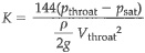
In sizing these nozzles, the best compromise between
Reynolds number, pressure loss, beta-ratio, and
deflection should be made without reducing the critical
cavitation coefficient K below 0.55 to avoid cavitation.
If the extraction steam is superheated, the extraction
flow can be determined by heat balance calculation. The
uncertainty of the result increases as the temperature rise
across the heater diminishes. It should be noted that errors
in temperature measurement will be translated into
errors in extraction flow. For instance, an error of 1°F
(O.5K) in the measured temperature rise of a heater with
an increase of 30°F (171K) will result in an error in extraction
flow of approximately 3.3%. In wet-steam cycles,
extraction flows can be determined from heater drain
flow measurements using calibrated flow measuring devices.
Nozzles can be used, and for the lowest pressure
heater, a diffusing cone should be installed downstream
of the nozzle because of the small pressure drop available.
In sizing these nozzles, the best compromise between
Reynolds number, pressure loss, beta-ratio, and
deflection should be made without reducing the critical
cavitation coefficient K below 0.55 to avoid cavitation.
 The measurement of the differential pressure requires care and should follow the precautions outlined in para. 7 for primary flow differential pressure measurement. Heater drain flows are often unsteady; to minimize errors due to such unsteady flow, reference should be made to paras. 3-9.1 through 3-9.4 for guidance on frequency of readings. For some secondary flows, such as moisture separator and reheater drains, a flow section may be impracticable because of cavitation caused by inadequate head. In these cases, the tracer technique can be used to measure the flow. The uncertainty for this method is about ±1%. 9.3 Feedwater Pump Turbine Steam Flow
Steam consumption of a feedwater pump turbine is
preferably measured as condensate if a separate condenser
is installed. However, in a cycle having a feedwater pump
driven by a turbine supplied with steam from the main
turbine, and where the condensate cannot be separately
measured, the steam supplied must be measured.
Feedwater pump turbine steam flow should be determined with instruments whose combined uncertainty is not greater than ±2% to limit the effect on heat rate to not more than ±0.5%. 9.4 packing Leak-Off Flow
An uncertainty no greater than ±5% is satisfactory for
packing flow measurements. This is attainable with appropriate,
commercially available uncalibrated instrumentation.
9.5 Turbine Interstage packing Leakage Flow
Opposed flow HP-IP turbines have shaft packing between
the HP and IP units to restrict steam flow from
the HP first stage exit zone to the IP inlet bowl. It is important
to assign values to this flow and its enthalpy because
it bypasses the reheater, affecting the calculation
of hot reheat steam flow and, thus, the turbine test heat
rate.
Since direct measurement of this leakage rate is not possible, a suitable approximation of this flow can be obtained by a special test procedure, involving enthalpy drop tests with selected combinations of throttle and hot reheat temperatures. In applying this method, it is assumed that the expansion of steam through the IP turbine takes place at the same efficiency regardless of (1) the starting state point and (2) the amount of the influence of the leakage from the HP turbine. Both of these items can be varied in a series of enthalpy drop tests in which different combinations of throttle and hot reheat temperatures are selected. The resulting "apparent" overall IP efficiencies (hot reheat state point to IP exhaust state point) are then analyzed to determine the most likely amount of leakage flow. It is helpful to include tests with the largest possible influence of this leakage on "apparent" IP efficiency by selecting combinations involving either high throttle temperature and low hot reheat temperature or high hot reheat temperature and low throttle temperature. In applying this method, each "apparent" IP efficiency must be adjusted to the level to be expected if two assumed amounts of interstage leakage (1 % and 4%) had not been present when the test was run. Plots of straight lines through several pairs of these points (lP efficiency vs. leakage flow in percent of hot reheat bowl flow) should show a convergence on the actual amount of leakage present. The adjustment of the "apparent" IP efficiency can be derived from Fig. 15, Effect of HP/IP Leakage on Measured IP Efficiency. The reader is cautioned that this method will include any other leakage (such as leakage across horizontal joints of internal parts) in addition to that through the packing. The enthalpy of any other leakage may not be known, but fortunately, the enthalpy of the leakage does not have a large effect on the result. This method should result in an uncertainty in interstage leakage flow of less than 1% of hot reheat flow. 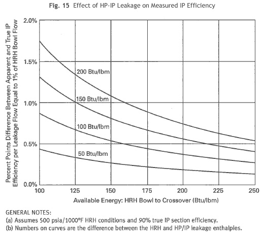
9.6 Air-Ejector Steam Flow
Steam-jet air-ejector steam flow may be determined
from the measured pressure and temperature of its steam
supply and known cross-sectional area of the jets. When
the steam supply is wet, it may be preferable to use the
design flow rates for the nozzle, corrected for supply pressure.
9.7 Feedwater Heater Leakage
Feedwater heater leakage can be determined by injecting
a tracer in the condensate entering the lowest
pressure heater and measuring the tracer concentration
in the heater drains.
If tracers are not used, such as in a fossil plant, feedwater heater leakage can be determined by c10sing the extraction valve, diverting the entering drain flow, and checking for a level change. 9.8 Heater Drain Flow
Extraction enthalpies can be determined by making
energy balances around individual feedwater heaters,
solving directly for enthalpy once the extraction flow
quantities are determined by measurement of heater
drain flows. The difference between the drain flow leaving
a heater and drain flow(s) into that heater is the extraction
flow from the turbine to that heater. See para.
9.2 for guidance in making the heater drain flow
measurements (see para. 9.8 below).
9.9 Two-Phase Steam-Water Mixtures
There are instances when it is desirable to measure
the flow rate of a two-phase mixture. An example is the
use of an orifice plate to measure the flow of wet heating
steam to the live steam reheater in a nuc1ear plant.
When this is done, the installation should be made with
all the care recommended in para. 9.1.
The calculation of the flow rate through the orifice requires that the familiar flow equation1 be adjusted to account for the presence of the water. Although there is no universally accepted adjustment resulting from the experimentation that has been carried out by several investigators, the following correlation is thought to be the best available for the applications required in this Code: 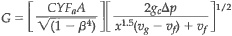 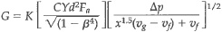 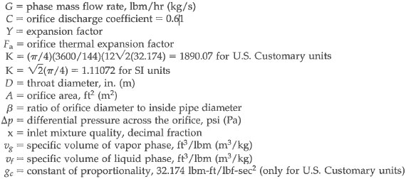 10 Measurement of Pressure10.1
The following list inc1udes the instruments to be used
for pressure measurement:
(a) Calibrated pressure transducers of the 0.10% accuracy class for all critical pressure measurements (see Fig. 16). Alternatively.
(1) for pressures above 35 psia (240 kPa), use calibrated
deadweight gages having a piston ratio of 10:1 or less.
(b) Random-type barometers for atmospheric pressure
measurement (see paras. 10.11 through 10.15).(2) for pressures below 35 psia (240 kPa), use calibrated manometers (see para. 10.7). (c) Absolute pressure transducers of the 0.10% accuracy class or better for exhaust pressure measurement of condensing turbines. Alternatively, absolute pressure gages, calibrated manometers (see para. 10.7), or differential pressure tranducers as described in para. 10.31 may be used. 
10.2
Calibrated pressure transducers of the 0.25% accuracy
class may be used to determine pressures where a high
degree of accuracy is not required as in the case of water
pressure at a test nozzle to determine density. Alternatively,
calibrated laboratory Bourdon gages may be
used in this application.
10.3 Transducers
Accurate pressure measurements with transducers require
care in use, proper maintenance, and proper installation.
It should be recognized that a transducer is,
in general, a delicate instrument and must be treated as
such.
10.3.1 Accuracy. The required accuracy of a
transducer for turbine testing should be determined by
calculating the effect an error in the pressure measurement
has on heat rate. Regardless of the transducer application,
it should be calibrated before and after every test.
10.3.2 Location. The transducer should be 10-
cated in a position that is free of vibration, dirt, and
where there are not likely to be large changes in ambient
temperature, such as may be caused by an outside
door. Where possible, transducers measuring pressures
above atmospheric should be mounted below the tap,
and those measuring pressure below atmospheric
should be mounted above the tap.
10.3.3 Zero Reading. li the transducer is sensitive
to changes in environment, such as temperature,
and a controlled capsule surrounds the sensing element,
the system should be given a minimum of 3 hr to stabilize
before readings are taken. A zero reading shall be
taken before and after each test run. The zero reading
shall not change more than 0.1 % of the reading observed
during the test run.
10.3.4 Differential-Pressure Transducers. Special
precautions should be observed when a transducer
is used to measure differential pressure. The transducer
selected for primary flow differential should have an error
no greater than 0.05% of full scale plus 0.010% of
reading (see para. 7).
10.4 Deadweight Gages
Deadweight gages shall be calibrated or standardized
before initial usage and thereafter as needed. The
weights shall be standardized by comparison with those
of a recognized national standards laboratory, such as
S weights of the National Institute of Standards and
Technology. When taking readings, the weights and
gage piston must be rotating to assure no fouling and
complete freedom of motion.
10.5 Bourdon Gages
Bourdon gages should be connected to the pressure
tap by an adequate coil to prevent high-temperature
fluid from reaching the gage.
10.6 Manometers and Barometers
A manometer may be of the U-tube type with scales
so arranged as to make it possible to read the level of
each leg and with the same size of tubing in both legs
or, alternatively, a reservoir-type manometer, which
may have a compensated scale.
10.7
Manometers required for random measurement,
such as primary flow, shall have scales, riders, and
verniers so that they may be read to 0.01 in. (0.25 mm).
For less random, scales should be readable to 0.05 in.
(1.25 mm). Before initial usage, U-tubes shall be checked
against standard scales to detect and record corrections
to apply to the scales, riders, and verniers. Reservoir-type
manometers for random measurement shall be
calibrated to detect and record the effects of capillarity
and the compensated scale; their zero shall be checked
carefully, with piping isolate d, using valving arranged
similar to that shown on Fig. 12(b) with the equalizing
valves open.
10.8
The tubes of all manometers should have an inside
bore of not less than 7/16 in. (11 mm) for subatmospheric
pressure or flow nozzle differentials and not less than
1/4 in. (6 mm) for other pressures. The larger the bore,
the smaller will be the correction for capillarity. Increased
sensitivity may be obtained by gently tapping
the manometer tubing during each observation.
10.9
If mercury is used in manometers, it shall be instrument
grade having less than one part per million .of
nonvolatile residue.
10.10
When a doubt arises as to the purity of the mercury
in the manometer, new instrument grade mercury shall
be substituted.
10.11
Barometric transducers of 0.01 in. (0.25 mm) mercury
resolution or random aneroid barometers may be used
to obtain barometer readings to which manometers are
to be referred. The barometers should be located in the
same room at the same elevation as that of the manometers
being used to measure pressures.
Barometer readings are to be corrected for difference in elevation, if any, between the barometer and any of the pressure reading devices that are to be referred to it. This correction shall be subtracted (added) at the rate of 0.01 in. Hg per 100 ft (2.5 mm Hg per 30 m) of elevation of the device above (below) the barometer. A laboratory or weather station of recognized standing may be used to obtain the readings with agreement of the parties of the test. 10.12
Barometers and manometers may require a correction
for capillary depression of the mercury. In some cases,
the scale of mercury-in-glass-type barometers are set to
correct for this, and no capillary correction need be
applied.
10.13
Random aneroid barometers or barometric transducers
with a minimum of 0.01 in. (0.25 mm) mercury
resolution are permissible for measurements of barometric
pressure. Prior to usage, these types of instruments
should be calibrated using a large bore mercury-in-glass
barometer over an extended period of time to
establish calibration corrections and repeatability of the
instrument. Before and after test calibrations are also
required. Transducers used for barometric pressure
measurements should be of the type with raised zero
and closely compressed range.
10.14
The barometer shall be checked by comparison before
and after the test to a barometer reading at a laboratory
or weather bureau station of recognized standing and
corrected to the same elevation.
10.15
Transducers of suitable accuracy, such as those described
in para. 10.1(c), may be used for exhaust-pressure
measurement.
10.16
Tightness of plpmg to transducers or exhaust-pressure
gages and manometers shall be checked by installing
a valve immediately adjacent to the exhaust easing
or conduit. The piping and valve should be so
arranged to avoid a pocket, with the valve stuffing box,
if any, exposed to the pressure in the gage side of the
piping when the valve is closed. At intervals during the
test or between tests, with full vacuum on the piping,
this valve is to be closed. If the reading falls at a rate not
greater than 1/4 in. (6 mm) in 5 mins, the gage piping
may be deemed to be satisfactorily tight.
10.17
For measurement arrangements utilizing air-filled
sensing lines, the low-pressure connecting piping shall
be arranged by the most direct route, pitch continuously
downward from the gage to the source of pressure, and
be without loops or pockets of any kind. This is required
to permit condensation in the sensing lines to drain back
to the source of pressure.
For low-pressure measurement systems using water-filled sensing lines, the connection of the measuring device should be at the same elevation or below the pressure tap to help prevent partial loss of the water leg in the sensing lines (refer to Figs. 17 and 18). 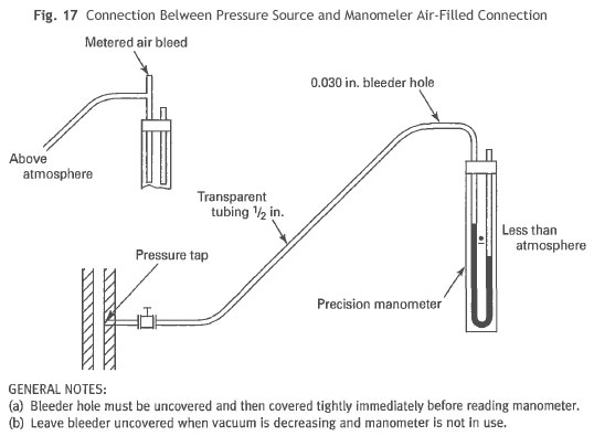
10.18
Precautions shall be taken that the manometer leg
subject to atmospheric pressure cannot be influenced by
any local atmospheric condition that would be different
from that to which the barometer is subjected. Ventilating
and draft fans can produce measurable differences
in atmospheric pressure. There may be cases where it is
necessary to pipe the atmospheric leg of the manometer
to an area unaffected by a fan.
10.19
Precautions shall be taken to ensure that both legs of a
manometer are subjected to the same ambient temperature
and that the fluid within a manometer or barometer
is at the same temperature as the thermometer by which
the fluid temperature is to be measured. Each of these instruments,
together with its corresponding thermometers,
shall be set up in-place and subjected to the
temperature conditions that exist at that location not less than
3 hr before a test is commenced.
10.20
For measurement of small differential pressures, such
as for sensors in piping utilizing impact and static taps,
special manometer fluids with a specific gravity approaching
that of water should be used. Precautions
should be taken that the manometer gasketing is compatible
with the fluid and if the sensor is in a vacuum
location, the fluid, must be suitable for vacuum service.
Manometers used for this type of service must have air-filled
sensing lines using small rate of air flow (0.5 to 2
cubic ft per hour) (4.9 x 10⁻³ to 19.6 x 10⁻³ m3/s) to
keep steam from condensing in the sensing lines. To
minimize blowing over the manometer fluid and for
zero checking the manometer, a three-way valve should
be used in the P1 (high pressure) and P2 (low pressure)
connections to the manometer.
10.21 Pressure Taps and Connecting Piping
Proper locations for all pressure taps must be selected
to promote accurate and reliable measurements of pressure.
Pressure taps at the turbine end of an extraction pipe
must be as dose to the turbine connection as practical but
far enough away to minimize the flow disturbances on
pressure readings. Therefore, pressure taps should not be
installed in the extraction nozzle. If the pressure measured
at the heater end of the extraction pipe is to be used
for computing heater terminal temperature difference, for
heater guarantee purposes, the pressure must be measured
at the heater nozzle. Source connections in the IP-LP
turbine crossover pipe or the LP turbine inlet serve as
a common point for IP and LP turbine efficiency determinations.
The best location is in a straight section as remote
from the IP turbine exhaust as practicable to minimize
the effect of stratification. All pressure taps should
be installed in a straight run of pipe as remote as possible
from upstream elbows or obstructions.
The amount of error caused by the pressure tap is a function of fluid velocity, type of fluid (compressible or incompressible), tap diameter, and configuration of the tap hole at the pipe wall. The total amount of error is generally small in steam turbine cycles because the velo city pressure component is small compared to the static pressure, and the error is on the order of 1% of the velocity pressure. Holes for measuring such pressures shall be drilled at right angles to the surface of the wall adjacent to the fluid. The hole diameter shall be no smaller than 1/4 in. (6 mm) and no larger than 1/2 in. (13 mm). The inner rim of the hole shall be free of burrs, leaving its edges sharp and square, or with a radius no greater than 0.06 times the hole diameter. For a length of at least twice its diameter, the hole shall be straight and of uniform bore. 10.22 Connecting Piping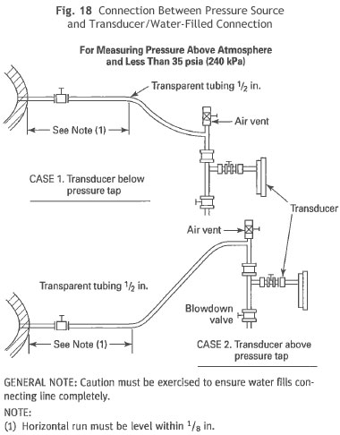 Connecting piping shall be not less than 3/8 in. (10 mm)
inside diameter, and 1/2 in. (13 mm) nominal outside diameter,
or equivalent tubing. The connecting piping or
tubing shall slope continuously from the level of the pressure
tap to the level of the transducer or gage, so as to
prevent air or water pockets; however, a water-loop seal
may be used when the pressure measuring device must
be located at a level above that of the pressure tap.
Connecting piping shall be not less than 3/8 in. (10 mm)
inside diameter, and 1/2 in. (13 mm) nominal outside diameter,
or equivalent tubing. The connecting piping or
tubing shall slope continuously from the level of the pressure
tap to the level of the transducer or gage, so as to
prevent air or water pockets; however, a water-loop seal
may be used when the pressure measuring device must
be located at a level above that of the pressure tap.
10.23 Air BleedsFor pressures which are below atmospheric pressure, the connecting piping shall contain means for bleeding air or other gas near the manometer, through which a very small rate of air flow may be metered for purging. Purging should be discontinued when readings are being taken if the purge flow affects the reading. This can be determined by comparing the readings with and without the air bleed. Such purging may be used for any higher pressure connections for which a suitable uniform source of air or other gas under pressure is available (see Fig. 17).10.24For any pressure instrument operating above atmospheric pressure, whose connecting piping is not purged, the piping shall include(a) reservoirs or long level sections of the connection near the turbine or steam pipe (b) suitable valves and nipples for flushing and venting the connections 10.25Pulsations of pressure shall not be damped by throttling or by the use of commercial dampeners.10.26
Deadweight gages and manometers with water-filled
connections are to be connected in accordance with Figs.
17 and 18. The water column correction in psi is the
product of 0.03612 and the height of column inches or,
in kPa, 0.9175 and the height of the column in millimeters,
with the appropriate algebraic sign and with temperature
correction from 32°F (0°C).
10.27 Initial Pressure Measurement
Initial steam pressure shall be measured in the main
steam line at or near the upstream boundary of the turbine
supplier's scope.
10.28
The steam strainer shall be known to be clean. If there
is a doubt about its cleanliness on the part of either of
the parties to the test, it shall be examined prior to the
test and cleaned, if necessary.
10.29 Exhaust Pressure Measurement
The exhaust static pressure of a condensing turbine is
to be measured at, or on either side of and adjacent to,
the exhaust joint. Special locations of demonstrable accuracy
may be used when agreed upon by the parties
to the test, but in no case shall there be fewer than two
such location, per exhaust annulus. When the test results
are not available to determine the proper location,
it is recommended that one pressure location be used
for each 16 ft2 (1.5 m2) of free area at the joint but in no
case more than eight for each exhaust annulus. The pressure
to be considered is the average of all of them. A
discrepancy in excess of 0.1 in. (2.5 mm) Hg between simultaneous
readings is to be cause for investigation.
Larger exhaust areas are common1y subject to spatial
variations exceeding 0.1 in. (2.5 mm) Hg.
10.30
The exhaust joint shall be the junction where the turbine
exhaust is attached to the flange of an expansion
joint or a condenser or welded to the condenser neck.
10.31 Absolute Pressure Gages
Differential pressure transducers with limited span or
absolute pressure transducers shall be used. If differential
pressure gages are used for measuring low absolute
pressures, they must be referenced to a vacuum of
30 μ of mercury or fewer. Alternatively, manometers of
the type known as absolute pressure gages may be used.
Transducers or absolute pressure gages shall be compared
with a manometer and barometer of known accuracy,
as specified in the following paragraph, immediately
before and after each test run. Errors found in
excess of 0.01 in. (0.25 mm) shall require investigation,
and the discrepancy shall be eliminated. If a discrepancy
in excess of the above limit is found between a manometer-
and-barometer combination and the transducer or
the absolute pressure gage, it shall not be assumed that
the error is in these instruments; both they and the
barometer shall be the subject of investigation.
10.32 Manometers
Manometers may also be used. The tubing shall be
not fewer than 7/16 in. (11 mm) bore at the point where
measurements are made. Ali the precautions required
for low-pressure measurements shall be employed. The
manometers shall have scales, riders, and verniers so
that they may be read to within 0.01 in. (0.25 mm). The
scales of manometers shall be calibrated so that they
may be correctly read to within 0.01 in. (0.25 mm).
For low-pressure measurements, the manometer must be scrupulously cleaned before the indicating fluid is introduced. Tubing may be dried by rinsing with alcohol or heating. 10.33
For small exhaust conduits, requiring not more than
four gages, where the walls are straight in the direction
of flow and flow is likely to be uniform, all of the pressure
connections may be located in the walls of the conduit.
Such connections shall be made in conformity
with para. 10.21, except that the hole diameter at
the open end shall be 3/8 in. (10 mm). The other end of
the hole may be of any size suitable for the pipe connection.
10.34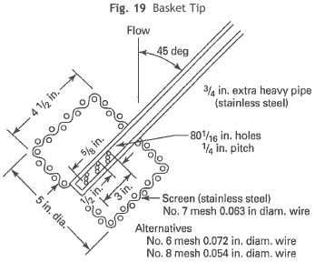 Where the above conditions do not exist, the pressure
connections should be carried into the interior of the
conduit and provided with basket tips or guide plates.
Basket tips are preferred. If the exhaust is provided with
ribs or braces traversing the steam space, some of the
gage piping connections may pass through them with
the opening flush and normal to the surface of the rib.
The terminals of exhaust-pressure-gage connections
shall be distributed over the entire exhaust-conduit area
and located so that they will be centered, as closely as
practicable, in equal areas. The basket tips should be installed
at a 45 deg angle, as shown in Fig. 19.
Where the above conditions do not exist, the pressure
connections should be carried into the interior of the
conduit and provided with basket tips or guide plates.
Basket tips are preferred. If the exhaust is provided with
ribs or braces traversing the steam space, some of the
gage piping connections may pass through them with
the opening flush and normal to the surface of the rib.
The terminals of exhaust-pressure-gage connections
shall be distributed over the entire exhaust-conduit area
and located so that they will be centered, as closely as
practicable, in equal areas. The basket tips should be installed
at a 45 deg angle, as shown in Fig. 19.Alternatively, guide plates may be used and should be arranged so that the steam flow is perpendicular to the pressure tap as shown in Fig. 20. Careful attention must be given to the location of basket tips and guide plates because pressures at certain points at the exhaust joint may be influenced by local high steam velocities. 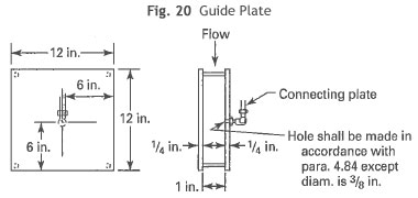
10.35
Upon agreement by the parties to the test, special
pressure taps of demonstrated accuracy may be employed
provided they are completely described in the
test report.
10.36 Absolute Pressure Determination
Measured pressures shall be corrected by the following,
as applicable:
(a) the instrument reading, using the proper conversion factors for the measuring fluid (refer to PTC 19.5) (b) the negative correction for manometer temperatures to 32°F (O°C) (c) the instrument correction, including any scale correction required (d) the gravity correction, correcting the reading to the value that would be obtained if gravity at the location of the instrument had the International Standard value of 32.174 ft/sec2 (9.80665 m/s2) (e) the water-leg correction (f) the measured barometric pressure, including the correction to the elevation of the gage 11 Measurement of Temperature11.1 Acceptable Systems
Acceptable temperature test measurement systems
shall meet a design and calibration criterion consistent
with the following. Careful consideration must be given
to the selection, installation, use, and interpretation of
the temperature measuring system. Direction as to
proper application of various systems can be found in
the Instrument and Apparatus Supplement, Part 3,
"Temperature Measurement," PTC 19.3. Any system
that can meet the requirement of repeatability in its calibration
and is proved accurate within the limits defined
for the particular temperature measurement shall be
deemed acceptable by the parties conducting the test.
Accuracy is further discussed in para. 11.4 and repeatability
of calibration in para. 11.7. PTC 6 Report,
Guidance for Evaluation of Measurement Uncertainty
in Performance Tests of Steam Turbines, does provide
several tables which may offer some guidance. In general,
Code-recommended temperature measurement
systems have an uncertainty of ±1°F (0.5 K).
11.2 Recommended Systems
Recommended temperature measurement systems
which have wide acceptance are generally defined as
(a) suitable platinum resistance-type thermometers, including proper leads calibrated and used in conjunction with random-bridge (0.03% accuracy) measuring instruments. (b) suitable thermocouples with continuous thermocouple wires and integral cold junctions calibrated and used in conjunction with a random high-quality digital voltmeter (±0.03% uncertainty or better). When using digital voltmeters, proper guarding procedures shall be followed to minimize errors introduced by noise. (c) calibrated thermocouples or random thermometers with an uncertainty not exceeding ±O.5°F (0.3 K) for cold junction ambient temperature reference measurements. 11.3 Locations
Location of temperature measurement sensors for enthalpy
determinations shall be as dose as practicable to
the points at which the corresponding pressures are
measured. Thermowells should be located downstream
of the pressure taps or, if upstream, not in the same longitudinal
plane. Temperature differences caused by
flow stratification shall be minimized by locating the
temperature sensor sufficiently downstream of an elbow,
or an extraction nozzle, to allow mixing of the
stratified flow before the measurement point.
Thermocouple and lead wires should not be run in the same cable trays as power lines to avoid sources of high electric fields. PTC 19.22 provides further guidance. Thermocouple lead wires shall not be subjected to large temperature gradients. Wire nonhomogeneities in the region of large temperature gradients can cause unacceptable measurement errors. 11.4 Influential Temperatures
Temperatures which have the most influence on test
results shall each be taken at two different points in dose
proximity but not in the same thermowell. Thermowells
must be installed within 4 pipe diameters and may be
in line, axially, if installed at least 2 pipe diameters apart.
If installed within 2 pipe diameters, the thermowells
must be at least 45 deg apart measured circumferentially.
The mean of the two readings shall be considered
the temperature of the fluid. Discrepancies between the
two readings must be resolved if these exceed 1°F (0.5
K). The recommended locations for these temperature
measurements are shown on the test instrumentation diagrams
of Figs. 9(a) through (e). The use of dual
thermocouple elements does not satisfy Code requirements
of critical temperature measurements at two different
points.
11.5 Wells
Thermowells shall be installed in conformity with the
ASME Boiler and Pressure Vessel or Piping Codes. Standards
for thermowells are given in PTC 19.3. Generally
(a) Tubes and wells shall be as thin as possible, consistent with safe stress and other ASME code requirements, and the inner diameters of the wells shall be dean and dry and free from corrosion or oxide. (b) The temperature-sensitive element shall fit closely in the well, being held firmly against the bottom. (c) Thermowells, and any extensions, shall be carefully covered with an insulating material to reduce air circulation and conduction of heat away from the tip. (d) Unless limited by design considerations, the temperature- sensitive element shall be immersed in the fluid at least 3 in. (75 mm) but not less than one-quarter of the pipe diameter. In pipes of less than 4 in. (100 mm) diameter, the element must be arranged axially in the pipe, by inserting it in an elbow or tee. If such fittings are not available, the piping shall be modified to render this possible. (e) In measuring the temperature of flowing media, the heat-receiving part of the apparatus shall not be in a dead space. 11.6 Cold Junctions
The temperature of cold junctions shall be measured
accurately. The accuracy with which the temperature of
the measuring junction is measured can be no greater
than the accuracy with which the temperature of the
cold junction is known. The cold junction temperature
shall be held at the ice-point or stable temperature of an
isothermal reference. When thermocouple cold junctions
are immersed in a water-ice bath, the bulb of a random
thermometer shall be immersed at the same level
as the cold junctions and in contact with them. Any deviation
from the ice-point shall be promptly corrected.
Each cold junction shall be electrically insulated. When the isothermal-cold-junction reference method is used, it shall employ an accurate temperature measurement of the reference heat sink acceptable to the parties conducting the test. Appropriate conversions for the isothermal cold junction temperature shall be used. When electronically controlled reference junctions are used, they shall have the ability to control the reference temperature to within ±0.05°ì P (0.03 K). Particular attention must be paid to reference junctions using terminals, since wire mismatching can introduce errors. Particular attention must be paid to the terminals of any referenced junction, since errors can be introduced by temperature variation, material properties, etc. By calibration, the overall reference system shall be verified to have an uncertainty of less than ±0.2 P (0.1 K). Isothermal thermocouple reference blocks furnished as part of digital systems may be used for turbine tests run in accordance with the Code, provided the accuracy is equivalent to the electronic reference junction. 11.7 Calibration
Calibration of thermocouples and resistance thermometers
shall be made before and after the test. If the
calibrations differ by more than 2°F (1 K), the temperature
measurement shall be in doubt, and resolution of
the difference by the parties to the test shall be made,
taking into consideration the effect on overall test accuracy.
During the calibration of any thermocouple, its
cold junction shall be held at the ice-point with an electronic
reference junction, isothermal reference junction,
or in a water-ice bath. The calibration shall be made by
an acceptable method, with the standard being traceable
to a recognized national standards laboratory, such as
the National Institute of Standards and Technology. Acceptable
calibration methods are to be conducted over
the temperature range in which the instrument is to be
used by one of the following procedures:
(a) By comparison with freezing-point baths of water, or of certified samples of metals with suitable melting points, such as tin, lead, and zinc. The temperature in the bath shall be read on a standard platinum resistance thermometer during the calibration to detect and reject a contaminated bath or an improper method. (b) By comparison with condensing-point baths of certified samples of substances with suitable boiling points, such as water and sulfur. The temperature in the bath shall be read on a standard platinum resistance thermometer during the calibration to detect and reject a contaminated bath or an improper method. The barometric pressure at the bath must be read, since boiling temperatures vary with atmospheric pressure. (c) At intermediate or extreme temperatures, by comparison with a standardized platinum resistance thermometer in a controlled-temperature copper block or other suitable source of uniform temperature. 11.8 Handling of Equipment
Random test equipment, such as thermocouples and
resistance thermometers and their potentiometers, bridges,
galvanometers, or other measuring instruments and
electronic reference junctions, must be carefully handled,
maintained, and periodically checked for uniformity
and stability. The potentiometers, together with
their standard cells and electronic reference junctions
shall be set up in position not less than 3 hr before a test
is started for subjection to the prevailing ambient temperature
and stabilizing the standard cells.
12 Methods of Determining Steam Quality
Steam quality cannot be measured directly. It can be
determined from pressure and enthalpy. The following
methods may be used, as applicable, to determine steam
quality.
(a) tracer technique, radioactive or nonradioactive (for throttle and extraction steam) (b) heater drain flow measurement and heat balance (extraction steam only) (c) throttling calorimeter (throttle steam only) Selection of one of these methods for determining steam quality must be based on the conditions of the steam-supply system under consideration, since each method has limitations that govern its use. 12.1 Tracer Technique
12.1.1 Method. Both radioactive and nonradioactive
tracers have been used for determining steam
quality of throttle and extraction steam of steam turbines
operating predominantly within the moisture region
with nuclear steam supply systems. A description of the
tracer technique is included in the following paragraphs.
Steam sampling, with respect to the type of probe, its location, and method of withdrawing the sample, shall be performed in accordance with the ASTM "Method of Sampling Steam," D 1066. Inherent limitations in the probe-sample techniques may make it difficult to obtain a representative steam line sample (also see PTC 19.11, Fans). The tracer technique has the advantage that it does not require a representative sample of the water-steam mixture. Only a sample of the water phase is required. The radioactive technique utilizes sodium 24 as the tracer. The principle of this technique is that the sodium salt is distributed by a large ratio (on the order of 107:1) into the liquid phase. Thus, by injecting a known concentration of radioactive salt at a known rate, sampling downstream from the injection point, and measuring the concentration of sodium in the liquid phase, it is possible to calculate the flow rate of the liquid phase. The enthalpy of the wet steam is determined from this measurement of water phase and extraction steam flows, which is calculated from an energy balance around the feedwater heater. Since the previous edition of the Code was issued, improvements have been made in developing a nonradioactive tracer that would overcome inherent limitations with radioactive tracers and be suitable for use in nuclear power plants having PWR or BWR nuclear steam supply systems. These limitations include a 15 hr half-life for sodium 24, as well as the need for relatively complex handling and analysis procedures. Sodium, lithium, and potassium salts have all been used as a nonradioactive tracer, depending on the specific type of reactor configuration and known elemental chemical background of the feedwater. In order to achieve sufficient accuracy utilizing the nonradioactive technique, proper selection and calibration of the injection and detection equipment are essential. (Reference "On-Line Measurement of Feedwater Flow and Steam Generator Moisture carry over using Chemical Tracers," ANS-ASME topical meeting April1988).
12.1.2 Implementation. Successful use of the
tracer technique requires the use of highly accurate instrumentation
for measuring mass and concentration of
tracer used. Aiso very important is the achievement of
good mixing of tracer injected into flow paths, so as to
obtain a homogenous sample from a downstream tap.
The use of a spray nozzle or tube to get the injected tracer into the interior ofthe pipe and away from the wall will promote more thorough mixing. Good mixing is also a function of distance between injection and sample points. The maximum distance available should be used. In some situations, the available distance may be inadequate for sufficiently accurate determination. For an extensive description of the tracer technique, including tracer requirements, design of inspection and sampling systems, radioactivity measurements, and computations, refer to PTC 19.5, which deals with measurement of water flow rates with tracers. An outline of various uses for steam quality determination is included below. Delay time, the time of transit of the tracer from the injection device to process tap to sample collection device, must be accounted. Therefore, measure the time of sampling, injection, and counting to the nearest minute.
12.1.3 Condensing Method. An appropriate
tracer, dissolved in the water-phase of wet steam at concentration
 , will be diluted by condensation of vapor.
After the steam is totally condensed, the tracer concentration
in the condenser will be Cc' The concentrations
are related by the balance. , will be diluted by condensation of vapor.
After the steam is totally condensed, the tracer concentration
in the condenser will be Cc' The concentrations
are related by the balance.
  = amount of water in wet steam = amount of water in wet steam = amount of condensate from wet steam = amount of condensate from wet steam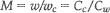
12.1.4 Throttle Steam Quality. Throttle steam
quality can be calculated from the quality and pressure
of the steam leaving the steam generator and throttle-steam
pressure, using a constant-enthalpy process, since
thermal radiation losses from the connecting steam piping
are generally negligible. The moisture in the steam
leaving the steam generator is the result of water
carryover. Thus, a tracer present in the steam generator
water will also be found in the steam leaving the steam
generator. In nonreheat cycles, the tracer will finally be
diluted in the total flow going back to the steam generator.
By the application of the condensing method,
steam generator exit moisture can be evaluated using
the second equation from para. 12.1.3.
In the case of reheat cycles, the error in throttle steam moisture determination caused by plating out of the tracer in the reheaters is negligible because the external moisture-separator effectiveness is essentially 100%. However, there is always the possibility of measuring the moisture carryover of the steam generator during special tests with the reheaters out of service. There are two methods of determining , the tracer
concentration at the water-steam interface or in the
carryover moisture. For steam interface with upper-shell
sample taps, this concentration may be measured
directly based on a sample taken from these taps. For
steam generators without upper-shell-sample taps,
is determined from a blowdown sample, which is corrected
for concentrating effects through the tube bundle
as shown in Figs. 21 and 22. Determination of the
concentration in the total flow,  , depends on the
arrangement of feedwater heaters. On cycles with cascading
heaters, total flow usually exists at the discharge
of the condensate pumps. On other cycles, if the demineralizers
are bypassed during the test, will be the
tracer concentration in the final feedwater. In all cases,
effects such as external-tracer sources feeding into the
cycle or losses of tracer, caused by demineralizers, must
be taken into account. , depends on the
arrangement of feedwater heaters. On cycles with cascading
heaters, total flow usually exists at the discharge
of the condensate pumps. On other cycles, if the demineralizers
are bypassed during the test, will be the
tracer concentration in the final feedwater. In all cases,
effects such as external-tracer sources feeding into the
cycle or losses of tracer, caused by demineralizers, must
be taken into account.
 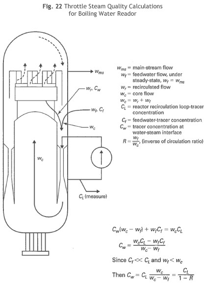
12.1.5 Extraction Enthalpy by Condensing Method.
The condensing method may also be used to determine
wet extraction steam enthalpy. This method is particularly
attractive if a suitable tracer is already present in
the steam path. However, error analysis shows that accurate
results can be obtained only on heaters without
cascading drains.
With this method extraction, enthalpy is evaluated from an energy balance and a tracer balance around the heaters. For the tracer balance, the concentrations of the tracer in all flows to and from the shell side of each heater are needed. Sampling the heater drains for concentration measurement of the tracer is fairly easy, as this is only single-phase flow. Sampling water out of the extraction line requires the same precautions as the case of the injection method.
12.1.6 Constant Rate Injection Method. A water
soluble tracer of concentration
 is injected at a constant
rate wini into the vapor-water flow where moisture
is to be measured. The concentration is measured
in the water phase downstream of the injection
point after adequate mixing has taken place. For this
condition, the following material balance can be written: is injected at a constant
rate wini into the vapor-water flow where moisture
is to be measured. The concentration is measured
in the water phase downstream of the injection
point after adequate mixing has taken place. For this
condition, the following material balance can be written:
 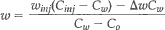 = mass flow rate of water in vapor-water mixture = mass flow rate of water in vapor-water mixture = initial concentration in the water phase at the
sampling points, before injection starts, due to natural amounts of tracer (background concentration) = initial concentration in the water phase at the
sampling points, before injection starts, due to natural amounts of tracer (background concentration) = change in water flow (condensation of vapor
due to injection of the cold-tracer solution) = change in water flow (condensation of vapor
due to injection of the cold-tracer solution)
 and and
 that the above equation is reduced to that the above equation is reduced to
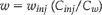
12.1.7 Extraction Enthalpy by Constant Rate Injection
Method. li the flow rate of the water phase in the
extraction line to a feedwater heater is known, wet-steam
enthalpy can be calculated by energy balance
around the heater, as shown in "Sample Calculations,"
PTC 6A, a separate publication of PTC Committee No.
6. The water flow rate can be measured with the constant-
rate injection method. Measuring flow rate and
concentration of the tracer solution and maintaining a
constant injection rate is comparatively simple. However,
the tracer concentration in the water-phase downstream
of the point of injection can be accurately determined
only if the tracer is well mixed and a sample of
the liquid-phase can be obtained.
(a) Injection Points. For the sample to be truly representative, the tracer must be homogeneously distributed in the water phase. The injection point should, therefore, be located immediately downstream of the extraction flange of the turbine, and the sampling point should be dose to the heater. A long run of pipe with several elbows will promote mixing. Use of a spray nozzle for injecting assures better mixing and is recommended. (b) Sampling Points. Since any condensed vapor in the sample will falsify the result, care must be taken in selecting the location of the sampling tap. At the conditions and velocities normally found in extraction lines, the water is not homogeneously distributed over the cross-section but is concentrated toward the pipe wall. This is a favorable distribution for water sampling; therefore, a simple wall tap should prove satisfactory. However, advantage should be taken of gravitational or centrifugal forces by locating the tap on the bottom side of the pipe or outer radius at the exit of an elbow, care being taken to avoid deadflow regions. All moisture removal points or other connections between the injection and sampling points shall be isolated while taking tracer data. Fig. 23 shows a typical installation of injection and sampling points. In cases where the extraction line is very short, such as with heaters installed in condenser necks, there is insufficient length of pipe for good mixing, and this method should not be attempted. 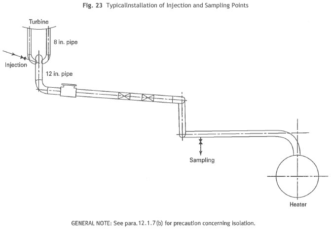
In such cases, it is recommended that the water sample
be taken from the heater drains. Also, in cycles with
pumped-ahead drains, the above method will yield accuracy
equal to the injection method without any additional
instrumentation. In cycles with drains cascading
to the condenser, the upstream drains must be diverted
directly to the condenser so as to accommodate total cascade
flow at full load. The diversion method should be
employed prior to the heat rate test.
(c) Sampling Flow Rates. The sampling flow rate must be adjusted so that entrainment and subsequent condensation of vapor is prevented. The maximum allowable sampling rate can be determined, for example, by analyzing the sampling stream for dissolved oxygen. Oxygen (20 ppm to 30 ppm) is naturally present in the steam from boiling water reactors as a result of radiolysis. The sampling flow rate shall be determined prior to conduct of the heat rate test. The oxygen content shall be measured for various sampling flow rates and plotted, as shown in Fig. 24. The flow rate at which steam starts to entrain in the sample is evidenced by a sharp rise in oxygen content. The validity of using oxygen or other suitable tracer as a means of tracing the vapor fraction is based on the distribution of oxygen between the liquid and vapor phases. At pressures fewer than 500 psia (3450 kPa), oxygen is almost entirely in the vapor-phase. In pressurized water reactor plants (PWR), a suitable tracer, such as xenon 133, could be used. However, it may be more convenient to add Na 24 and note the sample rate at which the concentration falls off, indicating entrainment of condensed steam.  12.1.8 Requirements for Tracers. For these
methods to give accurate results, tracers shall meet these
criteria.
12.1.8 Requirements for Tracers. For these
methods to give accurate results, tracers shall meet these
criteria.(a) soluble in water but essentially insoluble in steam (fewer than 0.1% at the test steam conditions) (b) nonvolatile (c) stable at the conditions existing in the turbine cycle (d) not adsorbed on internal surfaces (provided that the water is not evaporated completely) (e) mixed completely and homogeneously with all the water available at any instant The choice of the tracer is determined by the criteria mentioned in the foregoing, plus considerations of the effects of the tracer on materials in the cycle, and possible hazards to operating personnel. The generation of light-water reactors in use when this publication was prepared was designed for pressure and temperature levels that permit a number of tracers to meet these criteria. At higher pressure levels, it may be more difficult to meet these criteria, and other tracers may be necessary. Radioactive tracers are particularly attractive for application in nuclear power plants, where licensing required for possession and handling of radioactive materials presents no particular problem. Tracer concentrations of fewer than one part per billion can be accurately measured using gamma-counting techniques. For steam cycles with very low radioactive background, the tracer activity concentration required for accurate testing is very small; however, the tracer should be a short-lived isotope to eliminate long-term contamination problems. Since it is not practical to measure the concentration of the samples simultaneously, it will be necessary to apply a correction to the measured concentration of each sample to account for isotope decay. One of the tracers that meets these criteria is 15 hr Sodium 24. If the tracer technique is used to determine throttle and extraction steam quality and heater leakage, there is some advantage to using three different radioactive tracers. 12.2 Extraction Enthalpy by Heater Drain Flow by Heater Drain Flow and Heat Balance
The quality of steam in an extraction line can be determined
from a measured pressure and an enthalpy derived
from a heat balance around the heater. This requires
the measurement of the drain flows into and out
of the heater in question (see para. 9.7). These flows
can be measured by use of orifice plates nozzles, venturis,
or tracer. Care must be taken to avoid cavitation
in low-pressure heater drains (see para. 9.2).
12.3 Calorimeter Method
Observations by means of a properly constructed
calorimeter will provide the means for accurately calculating
the percentage moisture present in a given sample.
The difficulty is that there can never be assurance
that the sample is representative of the average condition
of the steam flowing in the pipe. Steam sampling,
with respect to the type of probe, its location, and
method of withdrawing the sample, shall be performed
in accordance with the ASTM "Method of Sampling
Steam," D-1066. Inherent limitations in the probe-sample
technique make it extremely difficult to obtain
a representative steam line sample. Techniques for sampling
are described in PTC 19.11, which should be consulted
if calorimeters are used.
13 Measurement of Speed13.1
For nonelectrical tests, or any test in which speed is
an important factor in the calculation or correction of
the test result, the speed shall be determined by means
of the following:
(a) an electronic-integrating counter that counts pulses generated by a magnetic or photoelectric pickup that responds to the passing of a device connected directly to the rotor of the turbine or driven machine, or by (b) a mechanical-integrating counter directly geared to some portion of the rotor of the turbine or driven machine 13.2
The electronic-integrating counter may be
(a) one that counts the revolutions for the entire period, or (b) one that counts for a brief period, such as an exact fraction of a second, then converts this to revolutions per minute, which is presented on a digital display until it is replaced by the next second' s conversion 13.3
If the counter integrates the revolutions for the whole
period of the test, the average speed shall be determined
from the total number of revolutions of the test period.
The time of the counter observation at the beginning and
end of the test shall be correct within 1 sec. The counter
reading at uniform intervals of time shall be recorded
with the corresponding speed in order to make certain
that the initial and final values are proper and direct-reading
device is not in gross error.
13.4
If the counter integrates the revolutions for short periods
and converts them to a display of revolutions per
minute, the average speed shall be calculated as the average
of readings of the display at uniform intervals
throughout the test period.
14 Measurement of Time14.1
The time of test periods and other observations may
be determined by the following:
(a) signals from a quartz digital dock, which has been sychronized with a master time signal if the tests require starting or stopping certain readings simultaneously. (b) observations of watches by the individual observers. 14.2
If signals from quartz watches are employed, the
signaling means shall be such that the signal may be
received within 1/2 sec of the desired time. Reliable
watches or docks shall be employed having an accuracy
with one minute per 24 hr period. Watches and docks
shall be synchronized with each other at the start of the
test.
15 Measurement of Water Levels
Water levels in the condenser hotwells, storage tanks,
and other points of water accumulation necessary for
the determination of changes in system storage shall be
measured to the closest 1/4 in. (6 mm) with appropriate
linear scales.
|
||||||